The Five Branches of Diden Robotics' Control Electronics: Circuit Design Started with In-House Actuators and Magnetic Feet
For actuators and sensors to work properly, the electrical system that delivers power and signals has to be in place first. This is how we designed circuits and firmware together around the demands of our own actuators and magnetic feet, how we made them withstand the electrical conditions of a working site, and how we made a delivered robot repairable without opening it.

Blog
A robot deployed on an industrial site such as a shipyard can run into problems that come from its electrical environment rather than from its own functions. When welding starts next to the robot, for example, communication errors appear and control boards restart on their own. This happens because the momentary high voltage produced by the welding arc travels through the robot frame and shifts the very voltage the circuits use as their reference.
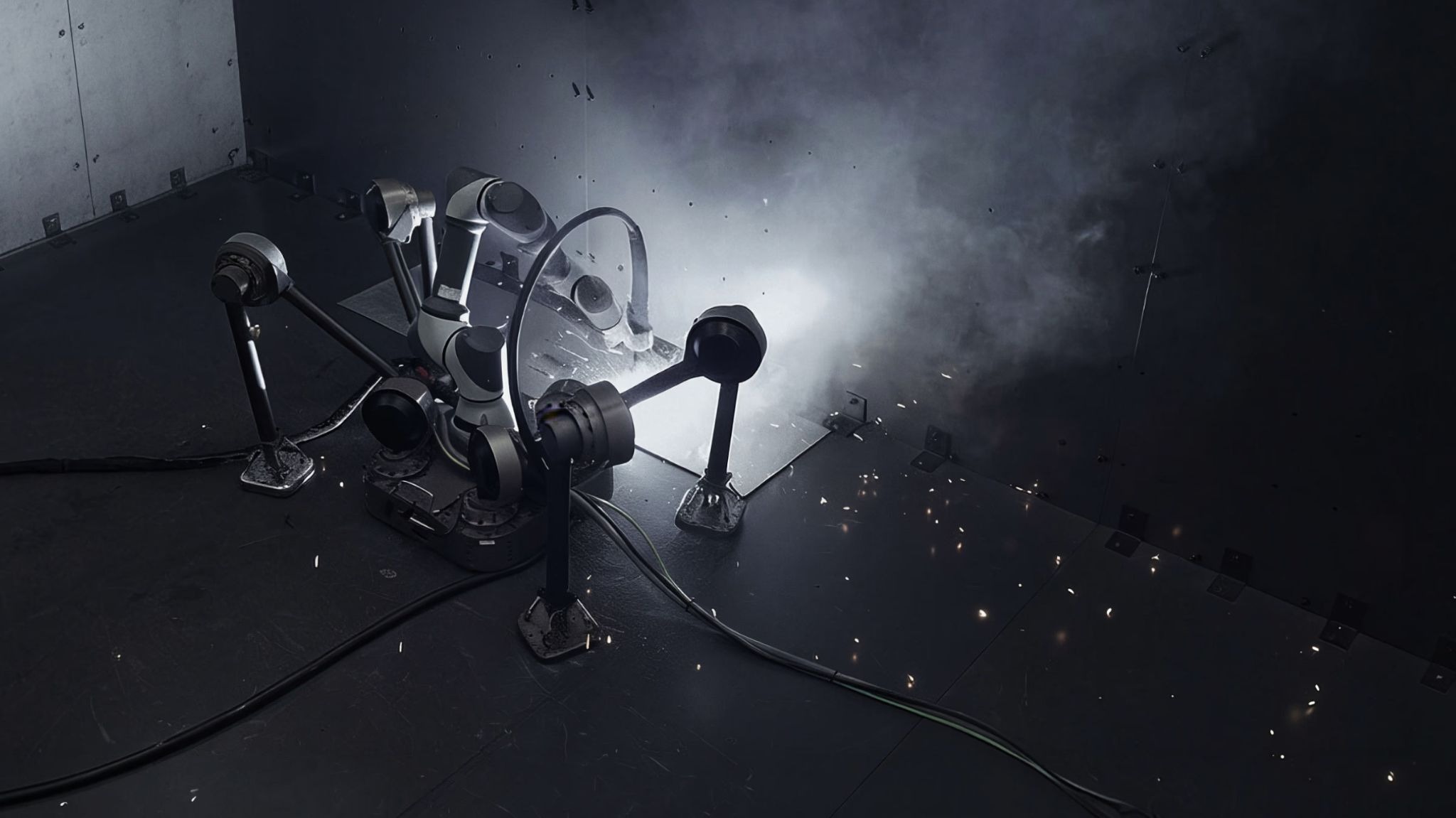
Diden Spider on an active welding floor, its in-house legged platform carrying a commercial collaborative robot as the task module ⓒDiden Robotics
There is a distinct domain inside the robot where this happens. It covers every electrical element in the machine: the boards, cables, connectors, and wiring. On top of them runs the firmware, written into the control boards. We call this domain the electronics.
The electronics are responsible for two things: power and signal. Power has to reach the actuator before the actuator can produce force, and the values a sensor measures have to travel without interruption before they can become a decision. The electronics form the routes that power and signal use. If one of those routes breaks, everything running on top of it stops.
Why a single break matters becomes clear when you look at how the robot's control is stacked. As we described in an earlier post on model-based control, our control is built as tasks and scenarios stacked above the shortest unit of low-level control. What matters here is that each layer runs on a different time scale.
Layer | What it does | Time scale |
|---|---|---|
Scenario | Orders tasks into a single work sequence | Minutes and above |
Task | Clearing an obstacle, moving between two points, taking a work-ready posture | Seconds |
Low-level control | Computes joint commands and produces the actual motion | Milliseconds |
All three layers run on the electronics. Low-level control is a loop that cycles in milliseconds, so if that loop stalls and several cycles go empty, the robot cannot hold its posture, and the minute-scale work sequence above it has nothing left to run on. The welding surge described earlier is exactly that case.
This post is about the electronics that support those three layers. We look, in order, at why we ended up building them in-house and at the five branches that work divides into.
Why We Build the Circuits Ourselves
An off-the-shelf motor comes with an off-the-shelf driver that runs it. Both are built to the same specification, and the manufacturer guarantees that the pair works. We designed our own actuators and magnetic feet, so that route was closed to us.
Start with the actuator. An off-the-shelf driver assumes an off-the-shelf motor, and that assumption carries a fixed control period and a fixed range of protective behavior. Our own actuators differ joint by joint in required torque and response, in gear ratio and inertia, and in the threshold at which overcurrent has to be cut. If the driver cannot accommodate those differences, the actuator cannot deliver the performance it is capable of.
For the magnetic feet, an equivalent product was hard to find. Our quadruped platform and our bipedal platform walk by holding onto steel plate with magnetic feet. Those feet use an electro-permanent magnet (EPM): two permanent magnets of different character sit in one magnetic circuit, and a short current pulse through a coil flips the magnetization of only the easier one. When both magnets point the same way, flux leaves the sole and grips the plate. When they oppose, flux circulates inside the magnet and the foot releases. Unlike a plain permanent magnet, it does not hold all the time, and unlike an electromagnet, it draws no power while holding. The demand exists only at the moment of change. Flipping the magnetization takes a large current delivered in a very short time.
That transition repeats for as long as the robot walks. The feet attach and release continuously, so the time it takes to switch is a key factor setting the lower bound on stride period. A slow transition means the robot cannot walk any faster, so the switching speed of the circuit ultimately governs walking speed.
Within the range we surveyed, nothing on the market met that condition. So we developed both the motor driver and the EPM driver in-house.
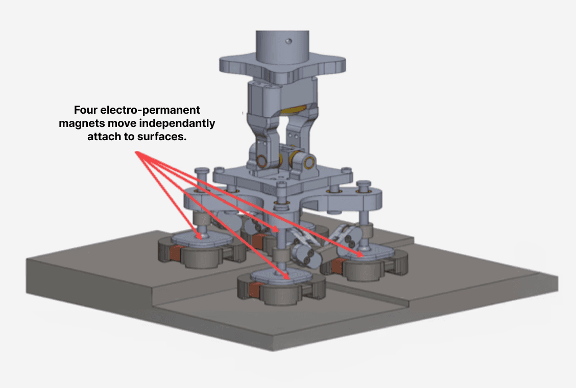
A magnetic foot that switches its holding force on and off within a single step ⓒDiden Robotics
Circuits alone are not enough to run actuators and feet we designed ourselves. What a circuit can deliver depends on the firmware running on it, and what the firmware can do is bounded by what the circuit supports. So we design circuits and firmware together, and that work divides into the five branches below.
What our electronics team owns | What it involves |
|---|---|
Circuit and board design | Designing power stages, motor drivers, sensor and communication circuits, and building the boards |
Firmware | Developing motor control, communication, and update functions that run on the control boards |
Wiring and connectors | Setting internal routing, building harnesses, selecting connectors |
Verification and quality control | Bringing up new boards, running functional tests, analyzing failures and feeding them back |
Test tool development | Building what verification needs, from parameter tools to automated inspection fixtures |
These five branches are interlocked. Routing has to be taken into account while the circuit is still being designed, and how a connector will be inspected later has to be settled while the connector is being chosen. Failures found during verification feed into revisions of the circuit design.
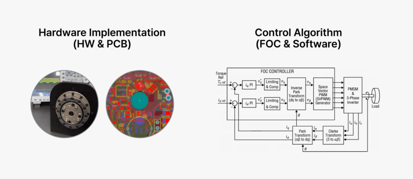
We develop the core elements in-house, from gearboxes and mechanisms through to circuits and firmware ⓒDiden Robotics
What follows looks at the problems that arise in the field across these five branches, why each one occurs, and the principle we use to solve it, in the order of power, signal, update and verification.
Problem One: How Wide Does the Power Path Need to Be?
Power comes first. An actuator draws a large current momentarily when it starts rotating from rest or absorbs an impact, and a high current continuously while holding a heavy load. Across the whole robot, the momentary current reaches several times the continuous current. That momentary value sets the reference for power stage design.
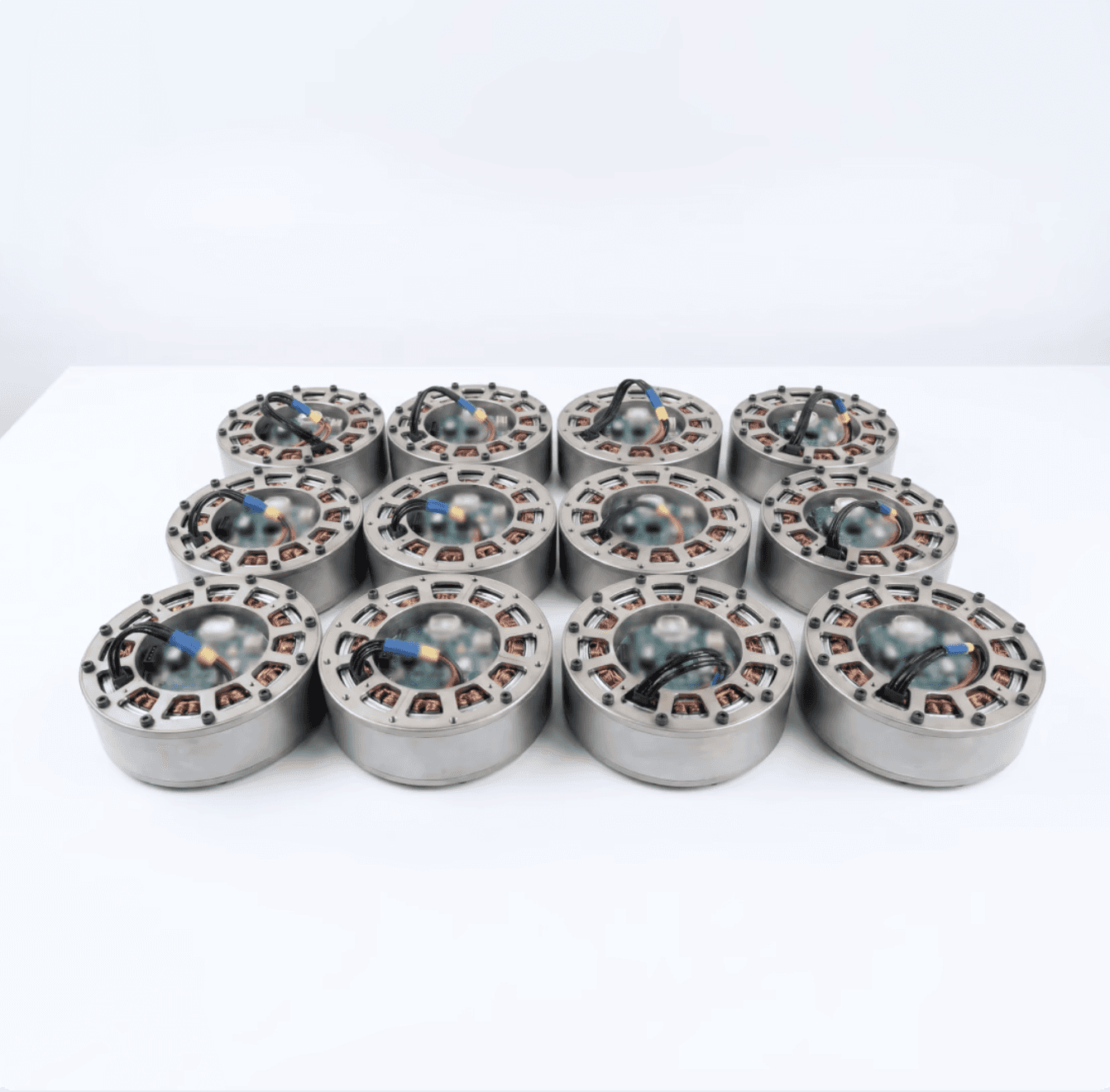
An in-house actuator whose current draw and protection thresholds are the starting point for power stage design ⓒDiden Robotics
If the board does not provide a path wide enough for that momentary current, two things follow. A narrower path has higher resistance, so heat builds at that point, and voltage drops at the same time. Of the two, voltage is what affects control directly.
The controller computes the required torque and issues a current command, and the driver adjusts voltage to produce that current. When voltage is lost along the path, the driver's voltage headroom shrinks, and at the moment the robot has to move fast and produce large force, it cannot meet the commanded current. If voltage collapses far enough during a current peak, the driver enters protection and stops on its own.
That gap between calculation and reality shows up in the robot's posture. For example, on a quadruped platform holding onto a wall, it shows up as slipping or tilting. However precise the control algorithm is, the robot still slips if power is not supplied to match.
Widening the path is the obvious answer, but it comes with its own constraints. A board is not a single thin sheet but alternating layers of copper and insulation. How much current a path can carry is set by its cross-section and by how well heat escapes at that point. Thicker copper is an option, but fine component routing makes thick-copper traces difficult on those layers, and board area puts a ceiling on width. If power runs on only one layer, the narrowest point on that layer becomes the bottleneck for the whole path, and current cannot detour into the other layers even when they are empty.
So we designed the power path by widening the trace and stitching several layers together with vias to enlarge the cross-section. The same area then carries more current, and as heat and voltage drop fall, so does the gap between what control commands and what actually comes out.
Problem Two: Current Flows, So Why Is the Signal Still Distorted?
Widen the power path and the current flows. Current flowing does not mean the signal always arrives intact. If a command from the control board is distorted on its way to the actuator, the robot performs a motion that was not commanded, or stops where it is.
We call the cause of that distortion noise. This noise arises inside the robot, and it also arrives from outside.
Start with noise generated inside the robot. Motor drive circuits work by switching current on and off quickly, and that switching produces high-frequency content that rides on the power and ground lines. The magnetic feet on our quadruped and bipedal platforms are more direct about it. The foot coil is a high-inductance load, so the instant a large pulse current is cut, the coil generates a high-voltage spike of its own, and the pulse current itself momentarily collapses the voltage on the power line. The action that produces the performance is the same action that produces the noise. Because the robot generates it, this noise exists before the machine ever reaches a site, and it does not disappear without a design change. We handle it by blocking it at the isolation stage we come to later, before it can reach the control side.
Next, noise arriving from outside. The representative case is the welding arc mentioned earlier. Welding melts metal by driving a large current through an arc, and when the arc strikes and breaks, it can produce a momentary voltage of several kilovolts, a surge. That surge travels through the air as an electromagnetic wave and couples into the circuits, and it also conducts through the steel structure the robot is standing on. The reason a surge disrupts control lies in grounding. Most signals in a circuit are read against ground, and even communication schemes that read the difference between two lines have a defined range in which the reference potential must stay. When the ground potential of the robot frame rises for an instant, the 0 V the circuits treat as reference moves with it. Once the reference moves, a signal sent correctly can still be read incorrectly. The result is a communication error, or a control board restarting on its own.
These two kinds of noise, arising inside and arriving from outside, cannot be handled by a single method, because noise is not one thing. Electrostatic discharge from a person or object touching the machine has very high voltage but little energy and lasts nanoseconds. Switching pulses are short, fast, and repetitive. Surges from an arc or a lightning strike last far longer than either and deliver far more energy. Because duration and energy differ, no single component blocks all of it. A component built to absorb large energy responds too slowly to catch a short pulse, and a fast-responding component damages itself when it takes large energy.
So instead of blocking with one component, we split the response into stages. A component that absorbs large energy sits at the front, followed by filters that strip remaining high-frequency content and isolation that electrically severs the two systems. Series impedance sits between the stages: while the faster downstream side clamps, the voltage across that impedance rises enough to fire the slower front element and hand it the bulk of the energy.
Each stage only has to bring the level down to what the next stage can take, and each component handles the kind of noise it is best suited to. What one stage does not fully attenuate is handled by the next.
Of these stages, isolation is what protects the control computer. The switching pulses and the voltage spikes from the magnetic feet described earlier are blocked at this stage. The principle is to electrically sever the high-voltage system feeding the motors from the low-voltage system the control computer uses. Power is transferred between the two systems without a direct current path, and signal lines crossing between them pass through isolation components so the grounds never join. Variation created by large motor currents then cannot reach the control computer's reference voltage.
On top of that, we provide a separate frame-ground discharge path. Between circuit ground and the robot frame sits a discharge component that stays open until voltage crosses a threshold. When a surge entering the frame lifts circuit ground with it, that component conducts, limits the difference between the two grounds, and returns the surge current to the frame rather than through the circuits. That path is built from a short, thick conductor to handle how fast a surge changes.
The same principle applies to grounding at the site. The rule is that the return path of the welding current and the ground of the control system must not share a conductive section. When a large current returning to the welder crosses a section, a potential difference appears across its ends, and if the control circuit is using that section as its reference, the reference voltage moves by the same amount. Grounding is a design-stage decision about where to connect and where to break.
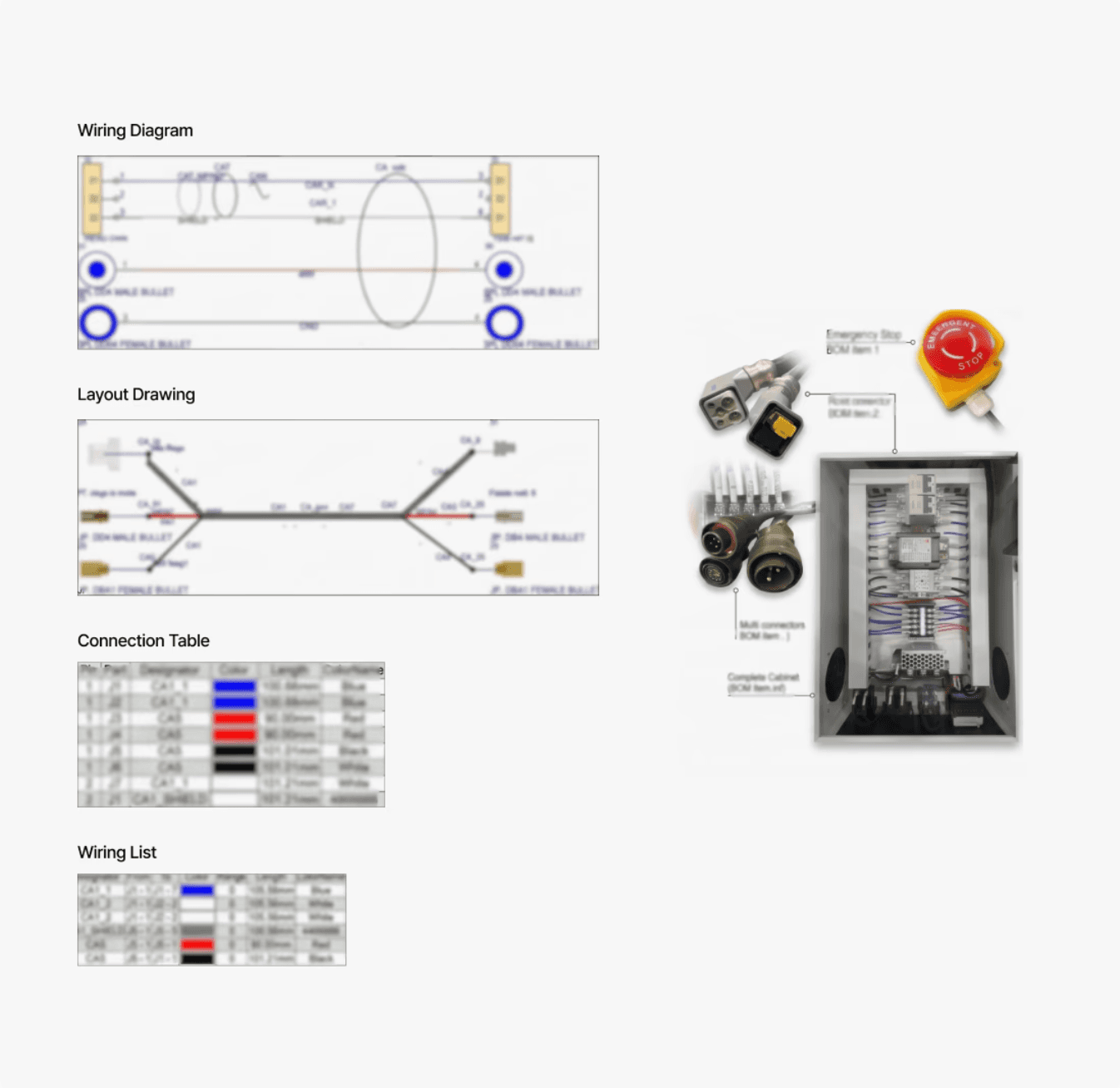
Electrical design documents that fix grounding and wiring routes together ⓒDiden Robotics
Problem Three: How Do You Fix a Robot That Has Already Shipped?
The first two problems belong to the time when the robot is being built. But once it is delivered, a different kind of problem appears.
At one point a requirement came back from the field: “a problem has to be fixable where the robot stands.” But a control board without a bootloader has to be touched directly to change its firmware. Open the cover, connect dedicated equipment to each board by cable, write the new code, reassemble, and repeat that as many times as there are control boards inside the robot. Fixing one function means going through that entire procedure again.
So we built a bootloader and an update tool. The bootloader is the first program to run when a control board powers on. It checks whether an update request is waiting, and if there is one, it receives the new code over the robot's own communication line, writes it, and restarts the board. If there is none, it runs the existing code as it is. The update tool is the program that drives that procedure from outside the robot, and it transmits code to multiple boards in sequence.
As a result, an update now finishes in minutes over the communication line, with no disassembly. The more important change is that this work can now be handled within a site schedule. Once there is a way to correct low-level control logic, improvement continues after delivery.
The bootloader is firmware, but circuit conditions have to be in place before it can exist at all. Which board is reachable over which communication line, whether a board can be recovered if power is lost mid-write, and how a board being updated is distinguished from the boards that are not on a shared line are all settled when circuit and firmware structure are decided together. How far the communication line reaches is set by the circuit, and whether the bootloader is preserved through a power loss mid-write and can receive code again is set by the firmware's memory layout. Because we design the control boards and the firmware ourselves, we were able to build that structure in from the start.
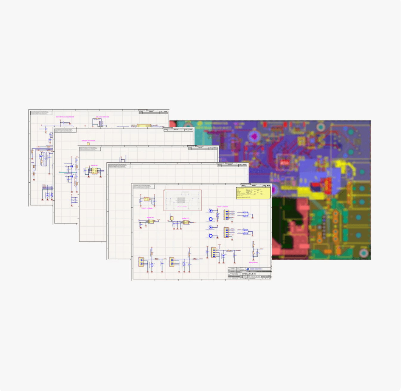
We develop circuits and firmware as a single process ⓒDiden Robotics
Building It Ourselves Means Verifying It Ourselves
One more thing grows as the in-house share grows: verification. Claiming performance means first owning the method that measures it. With an off-the-shelf part, you take the value the manufacturer guarantees. With a board and an actuator you designed, you have to produce that value yourself.
When a new board arrives, the work starts with bringing it up. We check that power rises correctly at each stage, that communication responds, and that each circuit block behaves as designed. A problem not caught here gets harder to trace the further downstream it travels.
Functional testing comes next. Actuators are measured under a real rotational load, because the value from a motor spinning free differs from the value under load, and the value that belongs on a datasheet is the loaded one.
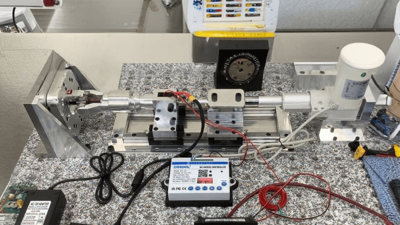
In-house test jig that measures actuator performance under an applied load ⓒDiden Robotics
The other axis of verification is certification. Certification looks like a check applied after the build, but in practice it is a design condition whose requirements have to be reflected from the moment the structure is decided. When one part falls outside a certification condition, replacing that part is not the end of it; the whole schedule slips.
For robots, that burden is unusually heavy. Electrical safety, machine safety, battery safety, radio frequency and electromagnetic compatibility all apply to a single product, and environmental durability against dust, water, temperature, humidity, vibration and corrosion is added on top. Each item asks for something different, and a design changed to satisfy one item can affect another.
Batteries are a clear example. Certification often includes an impact test. Passing it may require a protective structure. Add that structure and the external dimensions grow, so the space for the battery and the clearance the cables need have to be laid out again. One certification item ends up changing the mechanical design. Finding that chain late in the design costs a great deal to unwind, so the requirements go at the front and the design starts from there.
The measures described earlier come up again at this stage. Electromagnetic compatibility divides in two directions: noise the robot emits must not disturb nearby equipment, and the robot must withstand noise coming from around it. Isolation and ground separation are field measures in their own right, and at the same time they are designed with the noise-immunity requirement in mind. Whether the requirement is actually met is confirmed by testing. Environmental durability works the same way. It is a property you can only state as a number once repeated results under temperature, humidity, water ingress, and vibration have accumulated, so we put the tests into the design stage and are accumulating results.
Back to the Welding Floor
Return to the welding floor described at the start. What stops a robot there is not a simple functional problem. Four things have to hold for it to keep moving.
A path wide enough for the current the actuator demands
A route that blocks the noise the robot generates and diverts what comes in from outside
A way to fix a fault without opening the machine
A verification chain that proves the first three hold
None of the four appear directly on a datasheet. But the remaining datasheet entries do not hold without them, which is what makes all four essential.
The moment we decided to build our own actuators, the entire system that drives them became ours as well. Diden Robotics builds Physical AI for real industrial sites, and that starts with putting this system in place.
More from Diden Robotics

Robot Perception in Harsh Industrial Environments: Three Sensor Swaps and What Finally Decided It
Blog
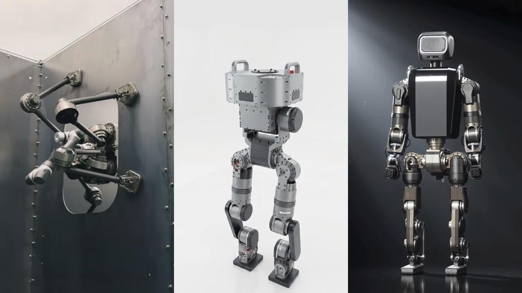
Why a Quadruped, a Biped, and a Humanoid All Walk the Same Way: Co-Designing Actuators and Learning
Blog
How a Robot Makes Moves No Human Has Ever Shown It
Blog
Why DIDEN Robotics Builds Its Actuators In-House
Blog